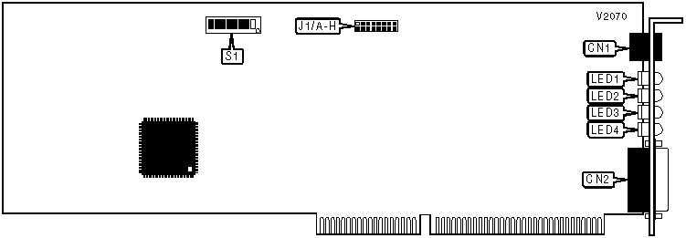
SDL COMMUNICATIONS, INC.
RISCOM/N2DDS
|
Card Type |
Serial/CSU/DSU |
|
Chip Set |
Hitachi HD64570 |
|
Maximum Onboard Memory |
256KB DRAM |
|
T1 Transfer Rate |
1.554Mbps |
|
Data Bus |
16-bit ISA |

|
CONNECTIONS | |||
|
Function |
Label |
Function |
Label |
|
T1 line |
CN1 |
RS-232 or RS-366 port |
CN2 |
|
USER CONFIGURABLE SETTINGS | |||
|
Function |
Label |
Position | |
| » |
Factory configured - do not alter |
S1/7 |
Unidentified |
| » |
Factory configured - do not alter |
S1/8 |
Unidentified |
|
INTERRUPT |
|
J1 is used to set the interrupt. Exact settings are unidentified. Interrupts 3, 4, 5, 9, 10, 11, 12, and 15 are available. |
|
BASE I/O ADDRESS | |||||||
|
Setting |
SW1/1 |
SW1/2 |
SW1/3 |
SW1/4 |
SW1/5 |
SW1/6 | |
|
100h |
On |
On |
On |
On |
Off |
On | |
|
110h |
Off |
On |
On |
On |
Off |
On | |
|
120h |
On |
Off |
On |
On |
Off |
On | |
|
130h |
Off |
Off |
On |
On |
Off |
On | |
|
140h |
On |
On |
Off |
On |
Off |
On | |
| » |
300h |
On |
On |
On |
On |
Off |
Off |
|
3B0h |
Off |
Off |
On |
Off |
Off |
Off | |
|
3C0h |
On |
On |
Off |
Off |
Off |
Off | |
|
3D0h |
Off |
On |
Off |
Off |
Off |
Off | |
|
3E0h |
On |
Off |
Off |
Off |
Off |
Off | |
|
3F0h |
Off |
Off |
Off |
Off |
Off |
Off | |
|
Note: A total of 48 base address settings are available. The switches are a binary representation of the decimal memory addresses. SW1/6 is the Most Significant Bit and switch SW1/1 is the Least Significant Bit. The switches have the following decimal values: SW1/6=512, SW1/5=256, SW1/4=128, SW1/3=64, SW1/2=32, SW1/1=16. Turn off the switches and add the values of the switches to obtain the correct memory address. (Off=1, On=0) | |||||||
|
DIAGNOSTIC LED(S) | |||
|
LED |
Color |
Status |
Condition |
|
LED1 |
Red |
On |
Network connection is broken |
|
LED1 |
Red |
Off |
Network connection is good |
|
LED2 |
Red |
N/A |
Not used |
|
LED3 |
Yellow |
On |
Card is in loopback mode |
|
LED3 |
Yellow |
Off |
Card is not in loopback mode |
|
LED4 |
Green |
Blinking |
Card processor is functioning normally |
|
LED4 |
Green |
Off |
Card processor is not functioning normally |