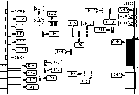
RAD DATA COMMUNICATIONS
ASM-24
|
Modem Type |
Data (synchronous) |
|
Maximum Data Rate |
144Kbps |
|
Data Bus |
External |
|
Data Modulation Protocol |
Proprietary |

|
CONNECTIONS | |||
|
Purpose |
Location |
Purpose |
Location |
|
V.24/V.35/X.21 |
CN1 |
Diagnostic test switch |
DIG |
|
AC power |
CN2 |
Analog loopback switch |
ANA |
|
Ground |
GND |
Remote loopback switch |
REM |
|
Receive |
RCV |
Test pattern |
PATT |
|
Transmit |
XMT | ||
|
ANALOG LOOPBACK | |
| Setting |
JP4 |
| » Enabled |
Pins 1 & 2 closed |
| Disabled |
Pins 2 & 3 closed |
|
BAUD RATE | |
| Setting |
SW1 |
| 144Kbps |
0 |
| 72Kbps |
1 |
| 112Kbps |
2 |
| 56Kbps |
3 |
| 128Kbps |
4 |
| » 64Kbps |
5 |
| 96Kbps |
6 |
| 48Kbps |
7 |
|
CD SENSITIVITY | |
| Setting |
JP5 |
| » High |
Pins 2 & 3 closed |
| Low |
Pins 1 & 2 closed |
|
CD SIGNAL | |
| Setting |
JP6 |
| CD normal |
Pins 2 & 3 closed |
| » CD forced high |
Pins 1 & 2 closed |
|
CHASSIS TO SIGNAL GROUND | |
| Setting |
JP8 |
| » Connected |
Pins 1 & 2 closed |
| Disconnected |
Pins 2 & 3 closed |
|
CLOCK SOURCE | |||
| Setting |
SW2/A |
SW2/B |
SW2/C |
| » Internal |
On |
Off |
Off |
| External |
Off |
On |
Off |
| Receive |
Off |
Off |
On |
|
ENABLE TOGGLE SWTICH | |
| Setting |
JP1 |
| » DIG, ANA, REM, PATT enabled |
Pins 1 & 2 closed |
| Disabled |
Pins 2 & 3 closed |
|
RECEIVE IMPEDANCE | |
| Setting |
JP13 |
| » 150omhs |
Pins 2 & 3 closed |
| High |
Pins 1 & 2 closed |
|
RECEIVE LEVEL | |
| Setting |
JP12 |
| » 0dBm |
Pins 1 & 2 closed |
| -6dBm |
Pins 2 & 3 closed |
|
REMOTE LOOPBACK | |
| Setting |
JP3 |
| » Enabled |
Pins 2 & 3 closed |
| Disabled |
Pins 1 & 2 closed |
|
REMOTE POWER FAILURE | |
| Setting |
JP10 |
| » Transmit RPF tone |
Pins 1 & 2 closed |
| Doesn’t transmit RPF tone |
Pins 2 & 3 closed |
|
RTS/CTS DELAY | |
| Setting |
JP7 |
| » 8ms |
Pins 1 & 2 closed |
| 70ms |
Pins 2 & 3 closed |
|
TRANSMIT IMPEDANCE | |
| Setting |
JP11 |
| » 150omhs |
Pins 1 & 2 closed |
| Low |
Pins 2 & 3 closed |
|
TRANSMIT LEVEL | |
| Setting |
JP9 |
| » 0dBm |
Pins 1 & 2 closed |
| -6dBm |
Pins 2 & 3 closed |
|
V.54 DELAY | |
| Setting |
JP2 |
| » On |
Pins 1 & 2 closed |
| Off |
Pins 2 & 3 closed |
|
DIAGNOSTIC LED(S) | |||
|
LED |
Color |
Status |
Condition |
|
PWR |
Green |
On |
Power is on |
|
PWR |
Green |
Off |
Power is off |
|
RTS |
Green |
On |
Request to Send enabled |
|
RTS |
Green |
Off |
Request to Send disabled |
|
TD |
Yellow |
On |
Modem is transmitting steady SPACE |
|
TD |
Yellow |
Off |
Modem is not transmitting data |
|
TD |
Yellow |
Blinking |
Modem is transmitting data |
|
RD |
Yellow |
On |
Modem is receiving steady SPACE |
|
RD |
Yellow |
Off |
Modem is not receiving data |
|
RD |
Yellow |
Blinking |
Modem is receiving data |
|
DCD |
Yellow |
On |
Carrier signal detected |
|
DCD |
Yellow |
Off |
Carrier signal not detected |
|
TEST |
Red |
On |
Modem in test mode |
|
TEST |
Red |
Off |
Modem not in test mode |
|
ERR |
Yellow |
On |
Errors in test pattern |
|
ERR |
Yellow |
Off |
Good test pattern |