CONTROLWARE COMMUNICATIONS SYSTEMS, INC.
CITAM
|
Card Type |
ISDN TA |
|
Chipset |
Unidentified |
|
ISDN Transfer Rate |
56Kbps x 2/64Kbps x 2 |
|
ISDN Protocol |
V.110, X.75 |
|
Switch Type |
1TR6, 5ESS, DMS100, DSS1, NI-1 |
|
Data Bus |
Serial |

|
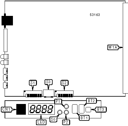
CONNECTIONS | |||
|
Function |
Label |
Function |
Label |
|
SELECT button |
BT1 |
ISDN S/T interface |
CN1 |
|
ENTER button |
BT2 |
LED display |
LED |
|
RESET button |
BT3 |
Header to interface board W1B |
W1A |
Note: Either CN1 or the ISDN interface on the installed interface board may be used, but not both. | |||
|
USER CONFIGURABLE SETTINGS | ||
|
Setting |
Label |
Position |
|
í Configuration may be changed via interface or front panel |
S1/1 |
Off |
|
Configuration may be changed via front panel supervisor only |
S1/1 |
On |
|
í ISDN connects with standard dialing |
S1/2 |
Off |
|
ISDN connects with S0FV (leased-line) |
S1/2 |
On |
|
í 1TR6 Service Indicator set for data transmission |
S1/3 |
Off |
|
1TR6 Service Indicator set for X.21 services |
S1/3 |
On |
|
í TA operates in synchronous mode |
S1/4 |
Off |
|
TA operates in asynchronous mode |
S1/4 |
On |
|
í Factory configured - do not alter (synchronous mode) |
S1/5 |
N/A |
|
USER CONFIGURABLE SETTINGS (CONíT) | ||
|
Setting |
Label |
Position |
|
í AT command set enabled (asynchronous mode) |
S1/8 |
On |
|
V.25bis command set enabled (asynchronous mode) |
S1/8 |
Off |
|
í X.21 command set enabled (synchronous mode) |
S1/8 |
On |
|
V.25bis command set enabled (synchronous mode) |
S1/8 |
Off |
|
í Factory configured - do not alter |
S2/1 |
On |
|
í CD signal forced high |
S2/6 |
Off |
|
CD signal high when connection is synchronized |
S2/6 |
On |
|
í DSR signal forced high |
S2/7 |
Off |
|
DSR signal high when connection is synchronized |
S2/7 |
On |
|
í Unit is a table-top version |
S2/8 |
Off |
|
Unit is a rack mount version |
s2/8 |
On |
|
DATA FORMAT SELECTION (ASYNCHRONOUS MODE) | |||
|
Setting |
S1/5 |
S1/6 |
S1/7 |
|
7 data bits, no parity, 1 stop bit |
Off |
On |
On |
|
7 data bits, even parity, 1 stop bit |
On |
On |
On |
|
8 data bits, no parity, 1 stop bit |
On |
On |
Off |
|
8 data bits, even parity, 1 stop bit |
Off |
Off |
On |
|
8 data bits, odd parity, 1 stop bit |
On |
Off |
On |
|
í 8 data bits, no parity, 2 stop bits |
Off |
Off |
Off |
|
8 data bits, even parity, 2 stop bits |
On |
Off |
Off |
|
8 data bits, odd parity, 2 stop bits |
Off |
On |
Off |
|
DATA FORMAT SELECTION (SYNCHRONOUS MODE) | ||
|
Setting |
S1/6 |
S1/7 |
|
ASCII character set, BSC encoding |
On |
On |
|
ASCII character set, HDLC encoding |
Off |
On |
|
EBCDIC character set, BSC encoding |
On |
Off |
|
í EBCDIC character set, HDLC encoding |
Off |
Off |
|
LINE SPEED | ||||
|
Setting |
S2/2 |
S2/3 |
S2/4 |
S2/5 |
|
300bps |
Off |
On |
Off |
On |
|
600bps |
On |
Off |
Off |
On |
|
1200bps |
Off |
Off |
Off |
On |
|
2400bps |
On |
On |
On |
Off |
|
4800bps |
Off |
On |
On |
Off |
|
9600bps |
On |
Off |
On |
Off |
|
19.2Kbps |
Off |
Off |
On |
Off |
|
38.4Kbps |
On |
On |
Off |
Off |
|
48Kbps |
Off |
On |
Off |
Off |
|
56Kbps |
On |
Off |
Off |
Off |
|
í 64Kbps |
Off |
Off |
Off |
Off |
Note: Asynchronous speeds may range from 300bps to 38.4Kbps, while synchronous speeds may range from 1200bps to 64Kbps. | ||||
|
SUBADDRESS SELECTION | |
|
Setting |
S3 |
|
EAZ 1 |
Position 1 |
|
EAZ 2 |
Position 2 |
|
EAZ 3 |
Position 3 |
|
EAZ 4 |
Position 4 |
|
EAZ 5 |
Position 5 |
|
EAZ 6 |
Position 6 |
|
EAZ 7 |
Position 7 |
|
EAZ 8 |
Position 8 |
|
TA is part of hunt group |
Position 0 |
Note: When adapter is set for leased-line mode, the EAZ must be set to 2. | |
|
DIAGNOSTIC LED(S) | |||
|
LED |
Color |
Status |
Condition |
|
S0 |
Yellow |
On |
ISDN connection is active |
|
S0 |
Yellow |
Blinking |
ISDN connection has been made but is not active |
|
S0 |
Yellow |
Off |
ISDN is not connected |
|
P1 |
Green |
On |
Port 1 is connected to ISDN |
|
P1 |
Green |
Blinking |
Port 1 has received an ISDN call but has not connected |
|
P1 |
Green |
Off |
Port 1 is not connected to ISDN |
|
P2 |
Green |
On |
Port 2 is connected to ISDN |
|
P2 |
Green |
Blinking |
Port 2 has received an ISDN call but has not connected |
|
P2 |
Green |
Off |
Port 2 is not connected to ISDN |
Note: P2 will have no function on models with only one port. | |||
|
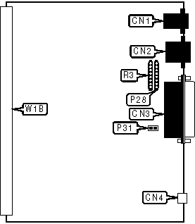
CONNECTIONS | |||
|
Function |
Label |
Function |
Label |
|
Supervisor port |
CN1 |
DC power in |
CN4 |
|
ISDN S/T interface |
CN2 |
Header to main board W1A |
W1B |
|
X.21 serial port |
CN3 | ||
|
USER CONFIGURABLE SETTINGS | ||
|
Setting |
Label |
Position |
|
í Signal ground not connected to chassis ground |
P31 |
Open |
|
Signal ground connected to chassis ground |
P31 |
Closed |
|
RECEIVER OPEN CIRCUIT FAILSAFE | ||
|
Setting |
P28 |
R3 |
|
í Enabled |
Not installed |
Installed |
|
Disabled |
Installed |
Not installed |
|
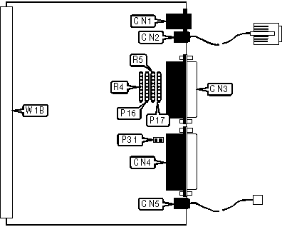
CONNECTIONS | |||
|
Function |
Label |
Function |
Label |
|
Supervisor port |
CN1 |
X.21 serial port 2 |
CN4 |
|
ISDN S/T interface |
CN2 |
DC power in |
CN5 |
|
X.21 serial port 1 |
CN3 |
Header to main board W1A |
W1B |
|
USER CONFIGURABLE SETTINGS | ||
|
Setting |
Label |
Position |
|
í Signal ground not connected to chassis ground |
P31 |
Open |
|
Signal ground connected to chassis ground |
P31 |
Closed |
|
PORT 1 RECEIVER OPEN CIRCUIT FAILSAFE | ||
|
Setting |
P16 |
R4 |
|
í Enabled |
Not installed |
Installed |
|
Disabled |
Installed |
Not installed |
|
PORT 2 RECEIVER OPEN CIRCUIT FAILSAFE | ||
|
Setting |
P17 |
R5 |
|
í Enabled |
Not installed |
Installed |
|
Disabled |
Installed |
Not installed |
|
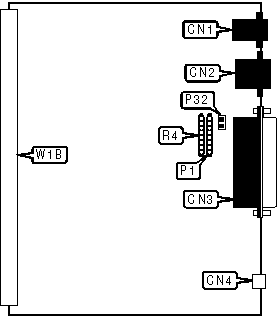
CONNECTIONS | |||
|
Function |
Label |
Function |
Label |
|
Supervisor port |
CN1 |
DC power in |
CN4 |
|
ISDN S/T interface |
CN2 |
Header to main board W1A |
W1B |
|
V.24 serial port |
CN3 | ||
|
USER CONFIGURABLE SETTINGS | ||
|
Setting |
Label |
Position |
|
í Signal ground not connected to chassis ground |
P32 |
Open |
|
Signal ground connected to chassis ground |
P32 |
Closed |
|
RECEIVER OPEN CIRCUIT FAILSAFE | ||
|
Setting |
P1 |
R4 |
|
í Enabled |
Not installed |
Installed |
|
Disabled |
Installed |
Not installed |
|
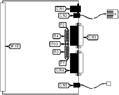
CONNECTIONS | |||
|
Function |
Label |
Function |
Label |
|
Supervisor port |
CN1 |
V.24 serial port 1 via DB-26 port |
CN4 |
|
ISDN S/T interface |
CN2 |
DC power in |
CN5 |
|
V.24 serial port 2 via DB-26 port |
CN3 |
Header to main board W1A |
W1B |
Note: Standard V.24 serial ports are provided on included adapter cables. | |||
|
USER CONFIGURABLE SETTINGS | ||
|
Setting |
Label |
Position |
|
í Signal ground not connected to chassis ground |
P33 |
Open |
|
Signal ground connected to chassis ground |
P33 |
Closed |
|
PORT 1 RECEIVER OPEN CIRCUIT FAILSAFE | ||
|
Setting |
P1 |
R3 |
|
í Enabled |
Not installed |
Installed |
|
Disabled |
Installed |
Not installed |
|
PORT 2 RECEIVER OPEN CIRCUIT FAILSAFE | ||
|
Setting |
P2 |
R4 |
|
í Enabled |
Not installed |
Installed |
|
Disabled |
Installed |
Not installed |
|
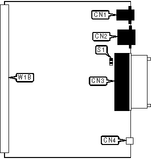
CONNECTIONS | |||
|
Function |
Label |
Function |
Label |
|
Supervisor port |
CN1 |
DC power in |
CN4 |
|
ISDN S/T interface |
CN2 |
Header to main board W1A |
W1B |
|
V.35 serial port |
CN3 | ||
|
USER CONFIGURABLE SETTINGS | ||
|
Setting |
Label |
Position |
|
í Signal ground not connected to chassis ground |
P32 |
Open |
|
Signal ground connected to chassis ground |
P32 |
Closed |
|
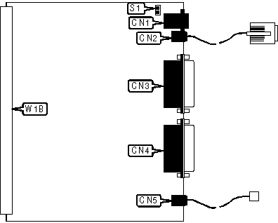
CONNECTIONS | |||
|
Function |
Label |
Function |
Label |
|
Supervisor port |
CN1 |
V.35 serial port 1 via DB-26 port |
CN4 |
|
ISDN S/T interface |
CN2 |
DC power in |
CN5 |
|
V.35 serial port 2 via DB-26 port |
CN3 |
Header to main board W1A |
W1B |
Note: Standard V.35 serial ports are provided on included adapter cables. | |||
|
USER CONFIGURABLE SETTINGS | ||
|
Setting |
Label |
Position |
|
í Signal ground not connected to chassis ground |
P32 |
Closed |
|
Signal ground connected to chassis ground |
P32 |
Open |
|
SUPPORTED STANDARD COMMANDS |
|
Basic AT Commands |
|
+++, A/ |
|
A, E, H, O, Q, V, X, Z |
|
&D, &F, &V, &W, &Z %I |
|
S-Registers |
|
S0, S1, S2, S3, S4, S5 |
|
V.25bis Commands |
|
CIC, CRI, CRS, DIC, PRN |
Note: See MHI help file for complete information. |
|
UNIDENTIFIED COMMANDS | |
|
Command |
Default |
|
%L |
0 |
|
%M |
0 |
Proprietary AT Command Set
|
ACCESS TYPE | |
|
Type: |
Configuration |
|
Format: |
AT [cmds] %Kn [cmds] |
|
Description: |
Selects the type of access for this ISDN line. |
|
Command |
Function |
|
í %K1 |
Line is intermittent dial-up. |
|
%K2 |
Line is semi-permanent dial-up. |
|
%K3 |
Line is time-link dial-up. |
|
ASYNC/SYNC MODE | |
|
Type: |
Configuration |
|
Format: |
AT [cmds] &Mn [cmds] |
|
Description: |
Selects whether the adapter is operating in asynchronous or synchronous mode. |
|
Command |
Function |
|
í &M0 |
Asynchronous mode selected. |
|
&M1 |
Asynchronous command mode, synchronous data mode at 600bps. |
|
&M2 |
Asynchronous command mode, synchronous data mode at 1200bps. |
|
&M3 |
Asynchronous command mode, synchronous data mode at 2400bps. |
|
&M4 |
Asynchronous command mode, synchronous data mode at 4800bps. |
|
&M5 |
Asynchronous command mode, synchronous data mode at 9600bps. |
|
&M6 |
Asynchronous command mode, synchronous data mode at 19.2Kbps. |
|
&M7 |
Asynchronous command mode, synchronous data mode at 38.4Kbps. |
|
&M8 |
Asynchronous command mode, synchronous data mode at 48Kbps. |
|
&M9 |
Asynchronous command mode, synchronous data mode at 56Kbps. |
|
&M10 |
Asynchronous command mode, synchronous data mode at 64Kbps. |
|
&M11 |
Synchronous data mode at 64Kbps with byte timing. |
|
&M13 |
Synchronous data mode at 128Kbps. |
|
CALLBACK DELAY | |
|
Type: |
Configuration |
|
Format: |
AT [cmds] %H=n [cmds] |
|
Default: |
Unidentified |
|
Range: |
0 - 255 |
|
Unit: |
1 second |
|
Description: |
Sets the amount of time that the adapter will wait after a call disconnects before initiating a callback sequence. |
|
CALLBACK MODE | |
|
Type: |
Configuration |
|
Format: |
AT [cmds] %Gn [cmds] |
|
Description: |
Selects when the adapter will call back an incoming call. |
|
Command |
Function |
|
í %G0 |
Neither initiate nor allow callback requests. |
|
%G1 |
Do not initiate callbacks but allow requests. |
|
%G2 |
Initiate callbacks but do not allow requests. |
|
%G3 |
Initiate callbacks and allow requests. |
|
CALL BUNDLING SOURCE | |
|
Type: |
Configuration |
|
Format: |
AT [cmds] %Jn [cmds] |
|
Description: |
Selects which stored number the modem will dial for the B2 channel when attempting call bundling. Executing %J0 will use the same number as was dialed for the B1 channel. |
|
CTS SIGNAL | |
|
Type: |
Configuration |
|
Format: |
AT [cmds] &Rn [cmds] |
|
Description: |
Controls the behaviour of the CTS signal. |
|
Command |
Function |
|
í &R0 |
CTS follows RTS. |
|
&R1 |
CTS forced high. |
|
&R2 |
CTS controlled by remote; high when connection is made at 48Kbps or less. |
|
DATA FORMAT | |
|
Type: |
Configuration |
|
Format: |
AT [cmds] %Nn [cmds] |
|
Description: |
Selects the format of the data from the serial port. |
|
Command |
Function |
|
%N0 |
7 data bits, no parity, 1 stop bit. |
|
%N1 |
7 data bits, even parity, 1 stop bit. |
|
%N2 |
8 data bits, odd parity, 1 stop bit. |
|
%N3 |
8 data bits, even parity, 1 stop bit. |
|
í %N4 |
8 data bits, no parity, 1 stop bit. |
|
%N5 |
8 data bits, odd parity, 2 stop bits. |
|
%N6 |
8 data bits, even parity, 2 stop bits. |
|
%N7 |
8 data bits, no parity, 2 stop bits. |
|
DCD SIGNAL | |
|
Type: |
Configuration |
|
Format: |
AT [cmds] &Cn [cmds] |
|
Description: |
Controls the behaviour of the DCD signal. |
|
Command |
Function |
|
í &C0 |
DCD high when call is synchronized. |
|
&C1 |
DCD forced high. |
|
&C2 |
DCD controlled by remote; high when connection is made at more than 48Kbps. |
|
DISPLAY INFORMATION | |
|
Type: |
Immediate |
|
Format: |
AT [cmds] In [cmds] |
|
Description: |
Displays information requested about the adapter. |
|
Command |
Function |
|
I |
Displays complete identification. |
|
I0 |
Displays information about the control firmware. |
|
I1 |
Displays information about the ISDN firmware. |
|
I2 |
Displays the version of the hardware. |
|
I3 |
Displays information about the interface board. |
|
DISPLAY STATUS | |
|
Type: |
Immediate |
|
Format: |
AT [cmds] %Sn [cmds] |
|
Description: |
Displays the status of the indicated part of the adapter. |
|
Command |
Function |
|
%S |
Display all information. |
|
%S0 |
Display port status. |
|
%S1 |
Display S0 status. |
|
%S2 |
Display last ISDN error code in hex. |
|
%S3 |
Display SPID 1. |
|
%S4 |
Display SPID 2. |
|
DSR SIGNAL | |
|
Type: |
Configuration |
|
Format: |
AT [cmds] &Sn [cmds] |
|
Description: |
Controls the behaviour of the DSR signal. |
|
Command |
Function |
|
í &S0 |
DSR high when connection is successful. |
|
&S1 |
DSR forced high. |
|
&S2 |
DSR controlled by remote; high when connection is made at more than 48Kbps. |
|
&S3 |
DSR high when connection is synchronized. |
|
ISDN B-CHANNEL MAPPING | |
|
Type: |
Configuration |
|
Format: |
AT [cmds] %Qn [cmds] |
|
Description: |
Selects how the adapter will map the B-channel subaddresses. |
|
Command |
Function |
|
í %Q0 |
B-channel mapping disabled. |
|
%Q1 |
B-channel mapping enabled. |
|
LOCAL SERIAL PORT SPEED | |
|
Type: |
Configuration |
|
Format: |
AT [cmds] %Rn [cmds] |
|
Description: |
Selects what speed the local serial port is operating at in asynchronous mode. |
|
Command |
Function |
|
%R0 |
Set speed to 300bps. |
|
%R1 |
Set speed to 600bps. |
|
%R2 |
Set speed to 1200bps. |
|
%R3 |
Set speed to 2400bps. |
|
%R4 |
Set speed to 4800bps. |
|
í %R5 |
Set speed to 9600bps. |
|
%R6 |
Set speed to 19.2Kbps. |
|
%R7 |
Set speed to 38.4Kbps. |
|
MATCH IN-BAND SPEED | |
|
Type: |
Configuration |
|
Format: |
AT [cmds] %An [cmds] |
|
Description: |
Selects whether the adapter may switch to match the in-band speed of the connection. |
|
Note: |
This command has no effect in asynchronous mode. |
|
Command |
Function |
|
%A0 |
Adapter may switch to lower speed. |
|
í %A1 |
Adapter may not switch speed. |
|
%A2 |
Adapter may switch to higher speed. |
|
%A3 |
Adapter may switch to any speed. |
|
MATCH BEARER SPEED | |
|
Type: |
Configuration |
|
Format: |
AT [cmds] %Bn [cmds] |
|
Description: |
Selects whether the adapter may switch to match the bearer speed of the connection. |
|
Note: |
This command has no effect in asynchronous mode. |
|
Command |
Function |
|
%B0 |
Adapter may switch to lower speed. |
|
í %B1 |
Bearer speed matching disabled. |
|
%B2 |
Adapter may switch to higher speed. |
|
%B3 |
Adapter may switch to any speed. |
|
%B4 |
Bearer speed matching enabled. |
|
PASSWORD CHECKING | |
|
Type: |
Configuration |
|
Format: |
AT [cmds] %Dn [cmds] |
|
Description: |
Selects when the adapter will require a password for configuration changes. |
|
Command |
Function |
|
í %D0 |
Require password for remote configuration changes only. |
|
%D1 |
Require password for all configuration changes. |
|
PASSWORD SET | |
|
Type: |
Configuration |
|
Format: |
AT %C=xxxx |
|
Description: |
Sets the password to a case-sensitive string of up to ten characters. If no string is entered the password is returned to its default. |
|
PROTOCOL | |
|
Type: |
Register |
|
Format: |
AT [cmds] S8=n [cmds] |
|
Description: |
Selects the bit rate adaptation protocol the adapter will use. |
|
Command |
Function |
|
S8=0 |
Adapter will use X.30. |
|
S8=1 |
Adapter will use V.110. |
|
SERVICE INDICATOR | |
|
Type: |
Register |
|
Format: |
AT [cmds] S6=n [cmds] |
|
Description: |
Sets the 1TR6 Service Indicator. |
|
Command |
Function |
|
í S6=3 |
1TR6 Service Indicator set for data transmission. |
|
S6=7 |
1TR6 Service Indicator set for X.21 services. |
|
SUBADDRESS | |
|
Type: |
Register |
|
Format: |
AT [cmds] S7=n [cmds] |
|
Description: |
Sets the subaddress to a value from 1 to 8. |
|
SUBADDRESS COPYING | |
|
Type: |
Configuration |
|
Format: |
AT [cmds] %En [cmds] |
|
Description: |
Selects whether the adapter will copy the subaddress to the call number. |
|
Command |
Function |
|
í %E0 |
Subaddress copying disabled. |
|
%E1 |
Subaddress copying enabled. |
|
SUBADDRESS - SETUP | |
|
Type: |
Configuration |
|
Format: |
AT [cmds] %Pn [cmds] |
|
Description: |
Selects which subaddress the adapter sends during call setup. |
|
Command |
Function |
|
í %P0 |
Adapter sends remote port subaddress. |
|
%P1 |
Adapter sends local port subaddress. |
|
SUBADDRESS SOURCE | |
|
Type: |
Configuration |
|
Format: |
AT [cmds] %On [cmds] |
|
Description: |
Selects the source of the subaddress sent to the remote system. |
|
Command |
Function |
|
í %O0 |
Taken from call number string. |
|
%O1 |
Global call sent in-band. |
|
%O2 |
Stored port subaddress sent in-band. |
|
%O3 |
Stored port subaddress sent in-band and during call setup. |
|
SWITCH TYPE | |
|
Type: |
Configuration |
|
Format: |
AT [cmds] %Fn [cmds] |
|
Description: |
Selects the switch type the adapter is connected to. |
|
Command |
Function |
|
í %F0 |
Adapter is connected to National NI-1 switch. |
|
%F1 |
Adapter is connected to AT&T 5E6 switch. |
|
%F2 |
Adapter is connected to AT&T 5E8 switch. |
|
%F3 |
Adapter is connected to Northern Telecom DMS-100 switch. |
Proprietary V.25bis Command Set
|
CALL REQUESTED NUMBER | |
|
Type: |
Immediate |
|
Format: |
CRN <#> |
|
Description: |
Dials the number given; it will ignore spaces and hyphens in the string; if the string is more than fifty characters long, a result of INV will be returned. |
|
Command |
Function |
|
CRN <#>*n |
Dials the number indicated and requests subaddress n. |
|
CRN <#>/n |
Dials the number indicated and requests subaddress n. |
|
CTS SIGNAL | |
|
Type: |
Configuration |
|
Format: |
PRO4;n |
|
Description: |
Controls the behaviour of the CTS signal. |
|
Command |
Function |
|
í PRO4;0 |
CTS follows RTS. |
|
PRO4;1 |
CTS forced high. |
|
PRO4;2 |
CTS controlled by remote; high when connection is made at 48Kbps or less. |
|
DCD SIGNAL | |
|
Type: |
Configuration |
|
Format: |
PRO6;n |
|
Description: |
Controls the behaviour of the DCD signal. |
|
Command |
Function |
|
í PRO6;0 |
DCD high when call is synchronized. |
|
PRO6;1 |
DCD forced high. |
|
PRO6;2 |
DCD controlled by remote; high when connection is made at more than 48Kbps. |
|
DISPLAY COMMAND SETTING | |||
|
Type: |
Immediate | ||
|
Format: |
RLO n | ||
|
Description: |
Displays the setting of the indicated option set with PROn; the adapter will respond with LSOn;a where a is the setting. Two values may be displayed that may not be set with PROn. They are listed below. If no value is given all options are listed. | ||
|
Command |
Value |
Meaning | |
|
RLO 8 |
0 |
Terminal is in asynchronous mode. | |
|
1 |
Terminal is in synchronous mode. | ||
|
RLO 9 |
3 |
1TR6 Service Indicator set for data transmission. | |
|
7 |
1TR6 Service Indicator set for X.21 services. | ||
|
DISPLAY STORED NUMBER | |
|
Type: |
Immediate |
|
Format: |
RLN n |
|
Description: |
Displays the telephone number stored in memory location n. If no location is specified, all stored numbers are listed. |
|
DSR SIGNAL | |
|
Type: |
Configuration |
|
Format: |
PRO5;n |
|
Description: |
Controls the behaviour of the DSR signal. |
|
Command |
Function |
|
í PRO5;0 |
DSR high when connection is successful. |
|
PRO5;1 |
DSR forced high. |
|
PRO5;2 |
DSR controlled by remote; high when connection is made at more than 48Kbps. |
|
PRO5;3 |
DSR high when connection is synchronized. |
|
ECHO | |
|
Type: |
Configuration |
|
Format: |
PRO2;n |
|
Description: |
Selects whether the modem will echo data received from the DTE back. |
|
Note: |
This command has no effect in synchronous mode. |
|
Command |
Function |
|
PRO2;0 |
Echo disabled. |
|
í PRO2;1 |
Echo enabled. |
|
INCOMING CALL INFORMATION | |
|
Type: |
Configuration |
|
Format: |
PRO7;n |
|
Description: |
Selects whether the INC message is V.25bis standard or displays extra information. |
|
Command |
Function |
|
PRO7;0 |
INC message is V.25bis standard. |
|
PRO7;1 |
INC message displays extra information. |
|
PROTOCOL | |
|
Type: |
Register |
|
Format: |
PRO3;n |
|
Description: |
Selects the bit rate adaptation protocol the adapter will use. |
|
Command |
Function |
|
PRO3;0 |
Adapter will use X.30. |
|
PRO3;1 |
Adapter will use V.110. |
|
RESET TO SWITCH DEFAULTS | |
|
Type: |
Immediate |
|
Format: |
PRO0;0 |
|
Description: |
Resets the configuration of the adapter to the settings of S1, S2, and S3. |
|
SUBADDRESS | |
|
Type: |
Configuration |
|
Format: |
PRO1;n |
|
Description: |
Sets the subaddress to a value from 1 to 8. |