ADTRAN
TSU 100
|
Card Type |
T1 CSU/DSU |
|
Chip Set |
Unidentified |
|
I/O Options |
Daughterboard connector |
|
Transfer Rate |
56/64Kbps x 23 |
|
Data Bus |
External |

|
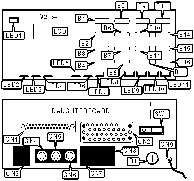
CONNECTIONS | |||
|
Function |
Label |
Function |
Label |
|
ENTER button |
B1 |
9 and CLEAR button |
B15 |
|
UP button |
B2 |
# and SHIFT button |
B16 |
|
DOWN button |
B3 |
RS-232/422 port |
CN1 |
|
CANCEL button |
B4 |
V.35 port |
CN2 |
|
1 and A button |
B5 |
T1 line out |
CN3 |
|
4 and D button |
B6 |
Test line in |
CN4 |
|
7 and REMOTE button |
B7 |
Test line out |
CN5 |
|
* and COPY button |
B8 |
Monitor test line |
CN6 |
|
2 and B button |
B9 |
Daisy chain in |
CN7 |
|
5 and E button |
B10 |
Daisy chain out |
CN8 |
|
8 and ALARM button |
B11 |
120V AC power |
CN9 |
|
0 and HOME button |
B12 |
Fuse, 1 / 2 A @ 250V |
R1 |
|
3 and C button |
B13 |
Power switch |
SW1 |
|
6 and F button |
B14 | ||
|
DIAGNOSTIC LED(S) | |||
|
LED |
Color |
Status |
Condition |
|
LED1 |
Red |
On |
CSU/DSU is being controlled by connected computer |
|
LED1 |
Red |
Off |
CSU/DSU is being controlled by front panel |
|
LED2 |
Green |
On |
DSU is operating normally |
|
LED2 |
Green |
Off |
DSU has detected an error |
|
LED3 |
Yellow |
On |
DSU is in test mode |
|
LED3 |
Yellow |
Off |
DSU is not in test mode |
|
LED4 |
Red |
On |
Alarm condition has occurred on DSU |
|
LED4 |
Red |
Off |
Alarm condition has not occurred on DSU |
|
LED5 |
Green |
On |
Daughterboard is operating normally |
|
LED5 |
Green |
Off |
Daughterboard has detected an error |
|
LED6 |
Yellow |
On |
Daughterboard is in test mode |
|
LED6 |
Yellow |
Off |
Daughterboard is not in test mode |
|
LED7 |
Red |
On |
Alarm condition has occurred on daughterboard |
|
LED7 |
Red |
Off |
Alarm condition has not occurred on daughterboard |
|
LED8 |
Green |
On |
CSU is operating normally |
|
LED8 |
Green |
Off |
CSU has detected an error |
|
LED9 |
Yellow |
On |
CSU is in test mode |
|
LED9 |
Yellow |
Off |
CSU is not in test mode |
|
LED10 |
Red |
On |
Error condition has occurred on CSU |
|
LED10 |
Red |
Off |
Error condition has not occurred on CSU |
|
LED11 |
Red |
On |
Alarm condition has occurred on CSU |
|
LED11 |
Red |
Off |
Alarm condition has not occurred on CSU |