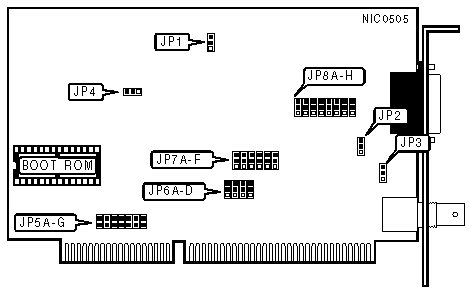
KATRON TECHNOLOGIES, INC.
ET-200
|
NIC Type |
Ethernet |
|
Transfer Rate |
10Mbps |
|
Data Bus |
16-bit ISA |
|
Topology |
Linear bus |
|
Wiring Type |
RG-58A/U 50ohm coaxial AUI transceiver via DB-15 port |
|
Boot ROM |
Available |

|
AUI ETHERNET VERSION | ||
|
Version |
JP1 | |
| » |
Version 2 |
Pins 1 & 2 Closed |
|
Version 1 |
Pins 2 & 3 Closed | |
|
Note:The ethernet version is dependent on the MAU you are using. There should be some indication of the ethernet version on the MAU.
| ||
|
SEGMENT LENGTH | ||
|
Maximum Length |
JP2 | |
| » |
185 meters |
Pins 1 & 2 Closed |
|
300 meters |
Pins 2 & 3 Closed | |
|
Note:Segment length is the total length of cable between the two farthest cards on the segment. Each card on the segment must have this option set the same. | ||
|
ONBOARD TERMINATOR | |||
|
Setting |
JP3 | ||
| » |
Disabled |
Pins 2 & 3 Closed | |
|
Enabled |
Pins 1 & 2 Closed | ||
|
Notes:If the card is on either end of a linear bus network segment, the onboard terminator can be used instead of using an external terminator.
| |||
|
COMPATIBILITY MODE | ||
|
Setting |
JP4 | |
| » |
Disabled |
Pins 1 & 2 Closed |
|
Enabled |
Pins 2 & 3 Closed | |
|
Note:On some systems the data bus timing is not truly IBM PC/AT compatible. If the card is not initializing, enabling compatibility mode may allow the card to operate properly.
| ||
|
INTERRUPT REQUEST | ||||||||
|
IRQ |
JP5A |
JP5B |
JP5C |
JP5D |
JP5E |
JP5F |
JP5G | |
|
2/9 |
Open |
Open |
Open |
Open |
Open |
Open |
Closed | |
| » |
3 |
Open |
Open |
Open |
Open |
Open |
Closed |
Open |
|
4 |
Open |
Open |
Open |
Open |
Closed |
Open |
Open | |
|
5 |
Open |
Open |
Open |
Closed |
Open |
Open |
Open | |
|
10 |
Open |
Open |
Closed |
Open |
Open |
Open |
Open | |
|
11 |
Open |
Closed |
Open |
Open |
Open |
Open |
Open | |
|
12 |
Closed |
Open |
Open |
Open |
Open |
Open |
Open | |
|
I/O BASE ADDRESS | |||||
|
Address |
JP6A |
JP6B |
JP6C |
JP6D | |
|
200h |
Open |
Open |
Open |
Pins 1 & 2 closed | |
|
220h |
Open |
Open |
Pins 1 & 2 closed |
Open | |
|
240h |
Open |
Pins 1 & 2 closed |
Open |
Open | |
|
260h |
Pins 1 & 2 closed |
Open |
Open |
Open | |
| » |
300h |
Open |
Open |
Open |
Pins 2 & 3 closed |
|
320h |
Open |
Open |
Pins 2 & 3 closed |
Open | |
|
340h |
Open |
Pins 2 & 3 closed |
Open |
Open | |
|
360h |
Pins 2 & 3 closed |
Open |
Open |
Open | |
|
BOOT ROM SIZE | |
|
Size |
JP7A |
|
8KB |
Pins 2 & 3 Closed |
|
16KB |
Pins 1 & 2 Closed |
|
BOOT ROM | ||
|
Setting |
JP7B | |
| » |
Disabled |
Pins 2 & 3 Closed |
|
Enabled |
Pins 1 & 2 Closed | |
|
BOOT ROM ADDRESS | |||||
|
Address |
JP7C |
JP7D |
JP7E |
JP7F | |
| » |
C8000h |
PIns 1 & 2 closed |
PIns 1 & 2 closed |
Pins 2 & 3 closed |
PIns 1 & 2 closed |
|
CC000h |
PIns 1 & 2 closed |
PIns 1 & 2 closed |
Pins 2 & 3 closed |
Pins 2 & 3 closed | |
|
D0000h |
PIns 1 & 2 closed |
Pins 2 & 3 closed |
PIns 1 & 2 closed |
PIns 1 & 2 closed | |
|
D4000h |
PIns 1 & 2 closed |
Pins 2 & 3 closed |
PIns 1 & 2 closed |
Pins 2 & 3 closed | |
|
D8000h |
PIns 1 & 2 closed |
Pins 2 & 3 closed |
Pins 2 & 3 closed |
PIns 1 & 2 closed | |
|
DC000h |
PIns 1 & 2 closed |
Pins 2 & 3 closed |
Pins 2 & 3 closed |
Pins 2 & 3 closed | |
|
CABLE TYPE | ||
|
Type |
JP8A - JP8H | |
| » |
RG-58A/U 50ohm coaxial |
Pins 2 & 3 closed |
|
AUI transceiver via DB-15 port |
Pins 1 & 2 closed | |