INNOVATIVE INTEGRATION
M44
|
Card Type |
Digital I/O card |
|
Chip Set |
TI |
|
Maximum Onboard Memory |
256KB Local, 2MB Global |
|
Data Bus |
32-bit PCI |
|
Card Size |
Full-length, full-height card |

|
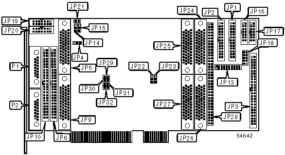
CONNECTIONS | |||
|
Function |
Label |
Function |
Label |
|
Serial port 4 |
JP1 |
JTAG connector |
JP19 |
|
Serial port 1 |
JP2 |
JTAG passthrough connector |
JP20 |
|
Unidentified |
JP3 |
50-pin board connector |
JP24 |
|
50-pin board connector |
JP5 |
50-pin board connector |
JP25 |
|
Unidentified |
JP6 |
50-pin board connector |
JP26 |
|
50-pin board connector |
JP9 |
50-pin board connector |
JP27 |
|
Unidentified |
JP10 |
Unidentified |
JP28 |
|
MUX channel 1 connector |
JP16 |
Unidentified |
P1 |
|
MUX channel 0 connector |
JP17 |
Unidentified |
P2 |
|
Digital I/O connector |
JP18 | ||
|
USER CONFIGURABLE SETTINGS | |||
|
Function |
Label |
Position | |
| » |
Onboard readback clock |
JP4 |
Pins 2 & 3 closed |
|
External readback clock |
JP4 |
Pins 1 & 2 closed | |
| » |
Serial port 1 bi-directional |
JP14 |
Pins 1 & 2 closed |
|
Serial port 1 output |
JP14 |
Pins 2 & 3 closed | |
| » |
Serial port 4 bi-directional |
JP15 |
Pins 1 & 2 closed |
|
Serial port 4 input |
JP15 |
Open | |
| » |
JTAG passthrough enabled |
JP21 |
Open |
|
JTAG passthrough disabled |
JP21 |
Closed | |
|
TOKEN FORCING SERIAL PORT 2 | |||
|
Setting |
JP29 |
JP31 | |
| » |
Forced |
Closed |
Closed |
|
Not forced |
Open |
Open | |
|
TOKEN FORCING SERIAL PORT 5 | |||
|
Setting |
JP30 |
JP32 | |
| » |
Forced |
Closed |
Closed |
|
Not forced |
Open |
Open | |
|
INPUT CLOCK SOURCE | |||
|
Source |
JP22 |
JP23 | |
| » |
On board 1MHz clock |
Pins 2 & 3 closed |
Pins 2 & 3 closed |
|
DDS synthesizer |
Pins 1 & 2 closed |
Pins 1 & 2 closed | |
|
PROCESSOR INTERRUPT IIOF0 | ||
|
Interrupt |
JP13 | |
| » |
External interrupt 0 |
Pins 4 & 6 closed |
|
9850 timebase |
Pins 1 & 3 closed | |
|
8254 channel 0 timebase |
Pins 2 & 4 closed | |
|
External trigger 0 |
Pins 3 & 5 closed | |
|
PROCESSOR INTERRUPT IIOF1 | ||
|
Interrupt |
JP13 | |
| » |
8254 channel 1 timebase |
Pins 8 & 10 closed |
|
External trigger 0 |
Pins 5 & 7 closed | |
|
External interrupt 0 |
Pins 6 & 8 closed | |
|
External interrupt 3 |
Pins 7 & 9 closed | |
|
PROCESSOR INTERRUPT IIOF2 | ||
|
Interrupt |
JP13 | |
| » |
External interrupt 1 |
Pins 12 & 14 closed |
|
External interrupt 3 |
Pins 9 & 11 closed | |
|
8245 channel 1 timebase |
Pins 10 & 12 closed | |
|
External digital I/O strobe |
Pins 11 & 13 closed | |
|
PROCESSOR INTERRUPT IIOF3 | ||
|
Interrupt |
JP13 | |
| » |
PCI interrupt |
Pins 15 & 17 closed |
|
8254 channel 2 timebase |
Pins 16 & 18 closed | |
|
External trigger 1 |
Pins 17 & 19 closed | |
|
External interrupt 2 |
Pins 18 & 20 closed | |


|
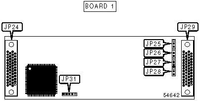
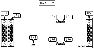
CONNECTIONS | |||
|
Function |
Label |
Function |
Label |
|
50-pin board connector |
JP2 |
50-pin board connector |
JP24 |
|
50-pin board connector |
JP3 |
50-pin board connector |
JP29 |
|
50-pin board connector |
JP4 | ||
|
OUTPUT MODE SELECTION | ||
|
Function |
Label |
Position |
|
Channel 0 stepper output |
JP25 |
Pins 1 & 2 closed |
|
Channel 0 analog output |
JP25 |
Pins 2 & 3 closed |
|
Channel 1 stepper output |
JP26 |
Pins 1 & 2 closed |
|
Channel 1 analog output |
JP26 |
Pins 2 & 3 closed |
|
Channel 2 stepper output |
JP27 |
Pins 1 & 2 closed |
|
Channel 2 analog output |
JP27 |
Pins 2 & 3 closed |
|
Channel 3 stepper output |
JP28 |
Pins 1 & 2 closed |
|
Channel 3 analog output |
JP28 |
Pins 2 & 3 closed |
|
UART SELECTION | ||
|
Setting |
Label |
Position |
|
Pin 47 = Ch. A Tx Clock |
JP5 |
Pins 1 & 2 closed |
|
Pin 47= Ch. A RTS |
JP5 |
Pins 2 & 3 closed |
|
Pin 43 = Ch. A Rx Clock |
JP6 |
Pins 1 & 2 closed |
|
Pin 43= Ch. A CTS |
JP6 |
Pins 2 & 3 closed |
|
Pin 39 = Ch. B Tx Clock |
JP7 |
Pins 1 & 2 closed |
|
Pin 39= Ch. B RTS |
JP7 |
Pins 2 & 3 closed |
|
Pin 35 = Ch. B Rx Clock |
JP8 |
Pins 1 & 2 closed |
|
Pin 35 = Ch. B CTS |
JP8 |
Pins 2 & 3 closed |
|
DIGITAL I/O READBACK CLOCK SETTINGS | ||
|
Setting |
Label |
Position |
|
External readback clock |
JP1 |
Pins 1 & 2 closed |
|
On-board readback clock |
JP1 |
Pins 2 & 3 closed |