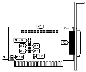
SCIENTIFIC MICRO SYSTEMS
OMTI 510, OMTI 510-HA-3, OMTI 510-HA-7
OMTI 512, OMTI 512-HA-3, OMTI 512-HA-7
|
| |
|
Data bus: |
8-bit, ISA |
|
Size: |
Half-length, half-height card |
|
Hard drive supported: |
Up to seven SCSI devices |
|
Floppy drives supported: |
None |

|
CONNECTIONS | |
|
Function |
Location |
|
50-pin SCSI connector - internal |
J1 |
|
37-pin SCSI connector - external (OMTI512 only) |
J2 |
|
USER CONFIGURABLE SETTINGS | |||
|
Function |
Location |
Setting | |
| » |
SCSI Busy signal enabled |
W1 |
pins 2 & 3 closed |
|
SCSI Busy signal disabled |
W1 |
pins 1 & 2 closed | |
| » |
SCSI Message signal enabled |
W2 |
pins 2 & 3 closed |
|
SCSI Message signal disabled |
W2 |
pins 1 & 2 closed | |
| » |
SCSI parity check enabled |
W4 |
pins 2 & 3 closed |
|
SCSI parity check disabled |
W4 |
pins 1 & 2 closed | |
|
USER CONFIGURABLE SETTINGS | |||
|
Function |
Location |
Setting | |
| » |
BIOS enabled |
W7 |
open |
|
BIOS disabled |
W7 |
closed | |
| » |
BIOS address is C800h |
W8 |
open |
|
BIOS address is CA00h |
W8 |
closed | |
| » |
28-pin EPROM type enabled |
W9 and W10 |
pins 1 & 2 closed |
|
24-pin EPROM type enabled |
W9 and W10 |
pins 2 & 3 closed* | |
| » |
SCSI Receive parity disabled |
W11 |
pins 1 & 2 closed |
|
SCSI Receive parity enabled |
W11 |
pins 2 & 3 closed | |
|
Note: Cut the foil trace between pins 1 & 2 on Jumpers W9 and W10 if closing pins 2 & 3 | |||
|
I/O PORT ADDRESS | |||
|
Address |
Jumper W6 |
Jumper W5 | |
| » |
320h |
open |
open |
|
324h |
open |
closed | |
|
328h |
closed |
open | |
|
32Ch |
closed |
closed | |
|
MISCELLANEOUS TECHNICAL NOTES |
|
Jumper W3 is not used and should remain factory configured with pins 1 & 2 in the closed position. Do not disable SCSI Busy and Message signals (Jumpers W1 and W2) |