PROMISE TECHNOLOGY, INC.
EIDE 4030 PLUS
|
| |
|
Data bus: |
32-bit VESA local bus |
|
Size: |
Three/quarter-length, full-height card |
|
Hard drive supported: |
Four IDE (AT) Interface drives |
|
Floppy drives supported: |
Two 360KB, 720KB, 1.2MB, 1.44MB drives |

|
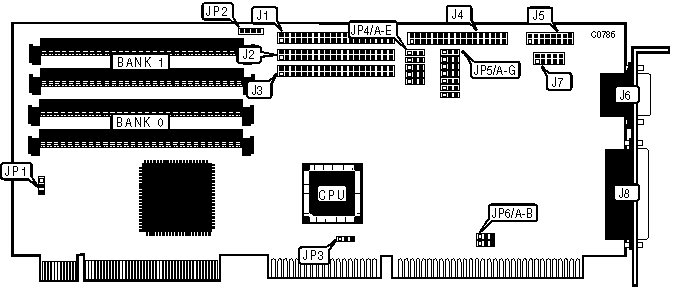
CONNECTIONS | |
|
Function |
Location |
|
40-pin primary VESA IDE(AT) interface connector |
J1 |
|
40-pin secondary VESA IDE(AT) interface connector |
J2 |
|
40-pin ISA ATAPI IDE(AT) interface connector |
J3 |
|
34-pin connector - floppy drive interface |
J4 |
|
16-pin connector - game port (external) |
J5 |
|
9-pin connector - serial port 1 (external) |
J6 |
|
10-pin connector - serial port 2 (internal) |
J7 |
|
25-pin parallel port (external) |
J8 |
|
4-pin connector - drive active LED |
JP2 |
|
Note: Connector J3 is used for IDE CD-ROM (ATAPI) and tape drives. | |
|
USER CONFIGURABLE SETTINGS | |||
|
Function |
Location |
Setting | |
| » |
VESA IDE is primary channel |
JP1 |
pins 1 & 2 closed |
|
VESA IDE is secondary channel |
JP1 |
pins 2 & 3 closed | |
|
VESA IDE channel is disabled |
JP1 |
all open | |
| » |
ISA IDE(AT) interrupt IRQ15 select |
JP3 |
pins 1 & 2 closed |
|
ISA IDE(AT) interrupt IRQ14 select |
JP3 |
pins 2 & 3 closed | |
| » |
Game port enabled |
JP4/A |
pins 1 & 2 closed |
|
Game port disabled |
JP4/A |
pins 2 & 3 closed | |
| » |
Factory configured - do not alter |
JP4/B |
pins 1 & 2 closed |
|
USER CONFIGURABLE SETTINGS (CONTINUED) | |||
|
Function |
Location |
Setting | |
| » |
Floppy drive interface enabled |
JP4/C |
pins 1 & 2 closed |
|
Floppy drive interface disabled |
JP4/C |
pins 2 & 3 closed | |
| » |
Parallel port interrupt select IRQ7 |
JP5/A |
pins 1 & 2 closed |
|
Parallel port interrupt select IRQ5 |
JP5/A |
pins 2 & 3 closed | |
|
PARALLEL PORT ADDRESS SELECTION | |||
|
Address |
JP5/B |
JP5/C | |
| » |
378h |
pins 2 & 3 closed |
pins 1 & 2 closed |
|
278h |
pins 1 & 2 closed |
pins 1 & 2 closed | |
|
3BCh |
pins 1 & 2 closed |
pins 2 & 3 closed | |
|
Disabled |
pins 2 & 3 closed |
pins 2 & 3 closed | |
|
PRIMARY SERIAL PORT ADDRESS SELECTION | |||
|
Address |
JP5/F |
JP5/G | |
| » |
3F8h (COM1) |
pins 1 & 2 closed |
pins 1 & 2 closed |
|
2F8h (COM2) |
pins 2 & 3 closed |
pins 1 & 2 closed | |
|
3E8h (COM3) |
pins 1 & 2 closed |
pins 2 & 3 closed | |
|
Disabled |
pins 2 & 3 closed |
pins 2 & 3 closed | |
|
SECONDARY SERIAL PORT ADDRESS SELECTION | |||
|
Address |
JP5/D |
JP5/E | |
| » |
2F8h (COM2) |
pins 1 & 2 closed |
pins 1 & 2 closed |
|
3F8h (COM1) |
pins 2 & 3 closed |
pins 1 & 2 closed | |
|
2E8h (COM3) |
pins 1 & 2 closed |
pins 2 & 3 closed | |
|
Disabled |
pins 2 & 3 closed |
pins 2 & 3 closed | |
|
ISA IDE CONFIGURATION | |||
|
Setting |
JP4/D |
JP4/E | |
| » |
ISA IDE(AT) interface is secondary interface |
pins 1 & 2 closed |
pins 1 & 2 closed |
|
ISA IDE(AT) interface is primary interface |
pins 1 & 2 closed |
pins 2 & 3 closed | |
|
ISA IDE(AT) interface is disabled |
pins 2 & 3 closed |
pins 2 & 3 closed | |
|
DMA CHANNEL CONFIGURATION | |||
|
DMA |
JP6/A |
JP6/B | |
| » |
3 |
pins 2 & 3 closed |
pins 2 & 3 closed |
|
1 |
pins 1 & 2 closed |
pins 1 & 2 closed | |
|
DRAM CONFIGURATION | ||
|
Size |
Bank 0 |
Bank 1 |
|
512KB |
(2) 256K x 9 |
NONE |
|
1MB |
(2) 256K x 9 |
(2) 256K x 9 |
|
2MB |
(2) 1M x 9 |
NONE |
|
4MB |
(2) 1M x 9 |
(2) 1M x 9 |
|
8MB |
(2) 4M x 9 |
NONE |
|
16MB |
(2) 4M x 9 |
(2) 4M x 9 |
|
Note: The EIDE 4030 PLUS must have at least 512KB installed in order to function. Optimum operation is achieved using 4 identical SIMM modules. | ||