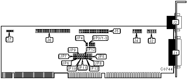
RELIALOGIC CORPORATION PRIVATE, LTD.
XL505
|
| |
|
Data bus: |
32-bit, VL-Bus |
|
Size: |
Three quarter-length, half-height card |
|
Hard drive supported: |
Two IDE (AT) interface drives |
|
Floppy drives supported: |
360KB, 720KB, 1.2MB, or 1.44MB drives |

|
CONNECTIONS | |
|
Function |
Location |
|
25-pin parallel port |
J1 |
|
9-pin serial port 1 (external)/10-pin serial port (internal) |
J2 |
|
10-pin serial port 2 - internal |
J4 |
|
34-pin connector - floppy drive |
J5 |
|
40-pin IDE(AT) interface |
J6 |
|
4-pin drive active LED |
J7 |
|
USER CONFIGURABLE SETTINGS | |||
|
Function |
Location |
Setting | |
| » |
Factory configured - do no alter |
JP4 |
open |
| » |
IDE interface enabled |
JP6 |
pins 1 & 2 closed |
|
IDE interface disabled |
JP6 |
pins 2 & 3 closed | |
| » |
Floppy drive interface enabled |
JP7 |
pins 1 & 2 closed |
|
Floppy drive interface disabled |
JP7 |
pins 2 & 3 closed | |
|
BASE ADDRESS SELECTION | ||||
|
Address |
JP3/1 |
JP3/2 |
JP3/3 | |
| » |
C800-CBFFh |
closed |
closed |
closed |
|
CC00-CFFFh |
open |
closed |
closed | |
|
D000-D3FFh |
closed |
open |
closed | |
|
D400-D7FFh |
open |
open |
closed | |
|
D800-DBFFh |
closed |
closed |
open | |
|
DC00-DFFFh |
open |
closed |
open | |
|
Disabled |
open |
open |
closed | |
|
Disabled |
open |
open |
open | |
|
PARALLEL PORT CONFIGURATION | |||
|
LPT |
JP12 |
JP13 | |
| » |
LPT2 |
pins 2 & 3 closed |
pins 1 & 2 closed |
|
LPT1 |
pins 1 & 2 closed |
pins 2 & 3 closed | |
|
LPT3 |
pins 1 & 2 closed |
pins 1 & 2 closed | |
|
Disabled |
pins 2 & 3 closed |
pins 2 & 3 closed | |
|
SERIAL PORT 1 & 2 CONFIGURATION | |||||
|
COM (Serial Port 1) |
COM (Serial Port 2) |
JP9 |
JP10 |
JP11 | |
| » |
COM1 |
COM2 |
pins 1 & 2 |
pins 1 & 2 |
pins 2 & 3 |
|
COM2 |
COM1 |
pins 1 & 2 |
pins 1 & 2 |
pins 1 & 2 | |
|
COM3 |
COM4 |
pins 2 & 3 |
pins 2 & 3 |
pins 1 & 2 | |
|
COM1 |
Disabled |
pins 1 & 2 |
pins 2 & 3 |
pins 2 & 3 | |
|
COM2 |
Disabled |
pins 2 & 3 |
pins 1 & 2 |
pins 1 & 2 | |
|
Disabled |
COM1 |
pins 1 & 2 |
pins 2 & 3 |
pins 1 & 2 | |
|
Disabled |
COM2 |
pins 2 & 3 |
pins 1 & 2 |
pins 2 & 3 | |
|
Disabled |
Disabled |
pins 2 & 3 |
pins 2 & 3 |
pins 2 & 3 | |
|
Note: Designated pins are in the closed position. | |||||
|
SERIAL PORT 1 & 2 INTERRUPT SELECTION | ||||
|
IRQ (Serial Port 1) |
IRQ (Serial Port 2) |
JP5 |
JP8 | |
| » |
4 |
3 |
pins 1 & 2 |
pins 2 & 3 |
|
3 |
4 |
pins 2 & 3 |
pins 1 & 2 | |
|
Note: Designated pins are in the closed position. | ||||
|
MISCELLANEOUS TECHNICAL NOTES |
|
IRQ 7 for the parallel port is factory configured and cannot be altered. |