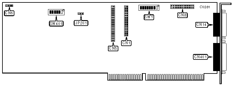
NCR CORPORATION
16-08-01
|
|
Data bus: 16-bit, ISA
Size: Full-length, full-height card
Hard drives supported: Two IDE (AT) Interface drives
Floppy drives supported: Two 360KB, 720KB, 1.2MB or 1.44MB drives

|
CONNECTIONS | |
|
Function |
Location |
|
34-pin control cable connector-floppy drive |
CN1 |
|
40-pin IDE (AT) Interface connector-internal |
CN5 |
|
4-pin connector-drive active LED |
CN6 |
|
26-pin dual serial port connector-internal |
CN8 |
|
25-pin parallel port (LPT1/2)-external |
CN14 |
|
15-pin VGA connector-external |
CN401 |
|
DUAL SERIAL PORT CONNECTOR (CN8) PIN ASSIGNMENT | ||
|
Serial Port 1 |
Serial Port 2 |
Signal |
|
15 |
23 |
Carrier Detect (CD) |
|
5 |
6 |
Receive Data (RxD) |
|
3 |
2 |
Transmit Data (TxD) |
|
14 |
10 |
Data Terminal Ready (DTR) |
|
13 |
21 |
Signal Ground |
|
11 |
4 |
Data Set Ready (DSR) |
|
7 |
12 |
Request To Send (RTS) |
|
9 |
25 |
Clear To Send (CTS) |
|
18 |
8 |
Ring Indicator (RI) |
|
22 |
22 |
Keyed |
|
USER CONFIGURABLE SETTINGS | |||
|
Function |
Location |
Setting | |
| » |
IRQ14 cleared after read block (SW1/switch 8 must be on) |
JP201 |
1 & 2 closed |
|
IRQ14 does not clear after read block |
JP201 |
2 & 3 closed | |
| » |
Floppy drive controller enabled |
SW1/switch 1 |
on |
|
Floppy drive controller disabled |
SW1/switch 1 |
off | |
| » |
Hard drive port address is 1F0-1F7h |
SW1/switch 2 |
off |
|
Hard drive port address is 170-177h |
SW1/switch 2 |
on | |
| » |
Parallel Port enabled |
SW1/switch 3 |
off |
|
Parallel Port disabled |
SW1/switch 3 |
on | |
| » |
Parallel Port (CN14) is LPT1 (378h) |
SW1/switch 4 |
off |
|
Parallel Port (CN14) is LPT1 (278h) |
SW1/switch 4 |
on | |
| » |
Serial Port 1 set to COM1 (3F8h) |
SW1/switch 5 |
off |
|
Serial Port disabled |
SW1/switch 5 |
on | |
| » |
Serial Port 2 set to COM2 (2F8h) |
SW1/switch 6 |
off |
|
Serial Port disabled |
SW1/switch 6 |
on | |
| » |
Interface Pin 34 Not used |
SW1/switch 7 |
off |
|
Ground (GND) enabled on Interface pin 34 |
SW1/switch 7 |
on | |
| » |
Hard drive controller enabled |
SW1/switch 8 |
off |
|
Hard drive controller disabled |
SW1/switch 8 |
on | |
| » |
Factory configured - do not alter |
SW401/switch 1 |
on |
| » |
Factory configured - do not alter |
SW401/switch 2 |
on |
| » |
AT BIOS compatible |
SW401/switch 3 |
on |
|
PS/2 BIOS compatible |
SW401/switch 3 |
off | |
| » |
Standard VGA mode |
SW401/switch 4 |
on |
|
Multisync VGA mode |
SW401/switch 4 |
off | |
| » |
VGA controller enabled |
SW401/switch 5 |
on |
|
VGA controller disabled |
SW401/switch 5 |
off | |
| » |
Standard Interrupt Handling |
SW401/switch 6 |
off |
|
Special Application Interrupt |
SW401/switch 6 |
on | |