DIVERSE LOGISTICS INC.
WINDJAMMER
|
Maximum Onboard Memory |
16MB DRAM (on optional cache controller) |
|
Hard Drives supported |
Fourteen SCSI-2 devices |
|
Floppy drives supported |
None |
|
Data Bus |
External |
|
Card Size |
14cm x 23 cm |
|
RAID levels supported |
0,1 |

|
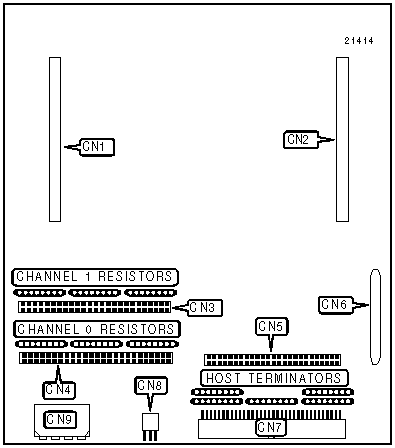
CONNECTIONS | |||
|
Function |
Location |
Function |
Location |
|
Proprietary connector - cache controller (optional) |
CN1 |
Proprietary connector - differential converter board (optional) |
CN6 |
|
Proprietary connector - cache controller (optional) |
CN2 |
68-pin SCSI connector to host - external |
CN7 |
|
50-pin SCSI connector channel 1 -- internal |
CN3 |
3-pin proprietary JST (RS-232) connector - see note below |
CN8 |
|
50-pin SCSI connector channel 0 - internal |
CN4 |
Power connector |
CN9 |
|
50-pin SCSI connector to host - external (optional) |
CN5 | ||
|
Note: CN8, the JST connector, can be connected to a DE-9 serial connector using a supplied cable that performs signal conversion. This cable allows the Windjammer to be connected to a VT100/VT220 terminal or terminal emulator. Note: CN6 or CN7 connects the Windjammer controller to the host system. CN6 allows the Windjammer to interface to host systems with differential SCSI ports via an optional differential converter board. Note: The location of hard drive connectors differs on some boards. If your Windjammer version has a top cover, channel 0 is located on the bottom of the rear panel and channel 1 on the top. | |||
|
TERMINATION CONFIGURATION | ||
|
Channel |
Controller Position |
Termination Required |
|
Controller to Host |
At end of SCSI bus |
Internal host terminators installed |
|
Controller to Host |
Not at end of SCSI bus |
Internal host terminators removed |
|
Controller to Host |
Active termination required |
Internal host terminators removed |
|
Channel 0 |
At end of SCSI bus |
Channel 0 internal terminators installed |
|
Channel 0 |
Not at end of SCSI bus |
Channel 0 internal terminators removed |
|
Channel 0 |
Active termination required |
Channel 0 internal terminators removed |
|
Channel 1 |
At end of SCSI bus |
Channel 1 internal terminators installed |
|
Channel 1 |
Not at end of SCSI bus |
Channel 1 internal terminators removed |
|
Channel 1 |
Active termination required |
Channel 1 internal terminators removed |
|
JST PINOUT | |
|
Pin |
Description |
|
1 |
Ground |
|
2 |
Receive Data |
|
3 |
Transmit Data |